


Short circuit Protection in DC Circuits
Authors: Viktor MARTINČIČ Graduated engineer, ETI Elektroelement
Mitja KOPRIVŠEK Master of Electrical Engineering, ETI Elektroelement
Branko PESAN, Graduated engineer, ETI Elektroelement
Abstract::
The importance of use of fuses as protection elements in DC circuits has increased recently. This article deals with some theoretical points and explanations of basic notions in DC circuits. Further on, some of the most common applications are described, where conventional shortcircuit protection is not sufficient enough and special requirements of designers or customers are necessary. Besides world trends in the field, some ETI new products, developed for DC circuits are presented.
1. INTRODUCTION - THEORY
The fuses are a universal protection element for AC and DC ciruits. Certainly, the capability to break a short circuit is different for AC and DC conditions of use. There is no universal formula to determine the highest rated DC voltage on the basis of the maximum fuse AC voltage data. To understand the proper use of DC circuit fuses, we have to know some of the basic information on their operation principle.
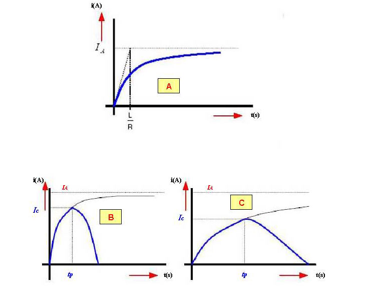
i=IA • (1-e-(L/R)t)
The value of available current IA, normally called expected current IP, is determined by the Ohms Law IA=U/R , but the value L/R= Τ is a time constant. The upper equation shows the L/R constant impact on the fusing time, where
Therefore, the higher the time constant L/R the lower the discharge di/dt and the longer the fusing phase.
Graph B shows that due to lower inductance, current increases faster and the fusing time is shorter in comparison with the conditions in the Graph C, where an example of current increase at high time constant is presented.
Incoming new technologies will require new knowledge on DC circuits. New and quickly developing fields to expect higher demand of fuses are:
- systems break-free power supply
- mobile telecommunication base stations
- photo-voltage systems (solar cells) – electric energy generation
- electric vehicles.
Most new applications are based on the resources that contain limited shortcircuit currents as to the conventional DC power supply which converts DC energy directly from the AC grid (unlimited), which is an advantage of the DC fuse selection and dimensioning.
DC SHORTCIRCUIT BREAK ANALYSIS IN VARIOUS FIELDS
One of basic fuse features is the capability to create high arcing voltage in case of shortciruit current, which exceeds the recovery voltage and forces the shortcircuit current to be reduced to zero instead of growing uncontrollably until expected short circuit current is reached.
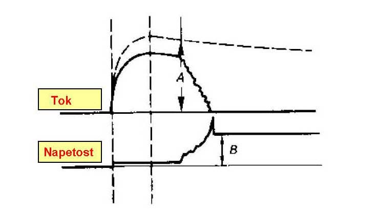
Marks:
A Expected shortcircuit current
B Recovery voltage
Generally speaking, the fuses are suitable for AC and DC current break. In the shortcircuit area (close to rated switch-off capability), the physical processes inside the fuse are identical in both cases.
The conditions in the overload area ( lower overload currents) are completely different for the AC and DC current. Regarding AC current, periodical crossing the zero will help with the electric arc extinction, but in the DC current fuse has to absorb the whole magnetic energy stored in the arc phase in case of a break. The consequence is that the DC break capability is inversely proportioned to the stored magnetic energy or the time constant of the circuit, respectively. The higher the time constant the lower the DC break capability. Normally, it is lower than the AC break capability.
Low voltage power fuses (mainly for industrial applications), see the standard IEC 60269-2, Ed.3, 11/2006) have a minimum break capability of 50 kA AC and 25 kA DC.
The value of the DC break capability is determined on the basis of the time constant 15ms, which is suitable for most industrial load and control circuits. The fuse break capability with higher time constant (with large DC motors applied) is adequately adapted – de-rated.Of course, in the circuits where no high inductance is expected (accumulator supply) the expected break capability can be increased.
However, the DC fuse break capabilty should be always considered in connection with the momentary circuit time constant.
Detailed information is usually given by the fuse producer or they can be tested. Typical time constants for some of the most often applications are enlisted in the table below:
| Application | Time constant (ms) |
| DC induction control and power circuits | ≤ 10 |
| Battery power resources and UPS systems | ≤ 5 |
| DC motors and drives | 20 do 40 |
| Magnets and generators | more than 1000 |
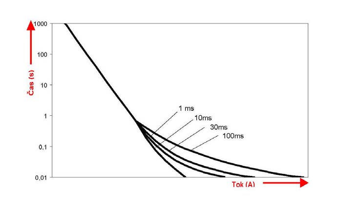
Average time-current characteristics given by the producer imply effective fusing current mid-values (r.m.s. values). These can be used for DC too. According to practice, they can be used in longer break times , for example, the fusing time is longer than 20-times time constant (over 300-400ms).
In transitional phenomena, the momentary and effective values can be much more different. Therefore, the time-current features depend on the time constant. (see the figure at the end of this chapter).

 ETI d.d. NEW PRODUCT ASSORTMENT
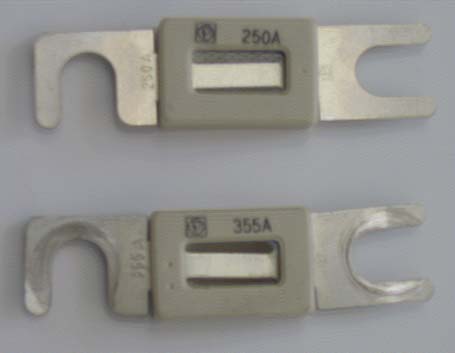
Leading world fuse producers have a wide range of fuse assortment to be used in DC circuits. Although not yet known in Europe, the field is the most developed in the USA. To support that, most DC fuses have been developed in the dimensions rarely found in Europe. Some examples are shown in the following two figures below.
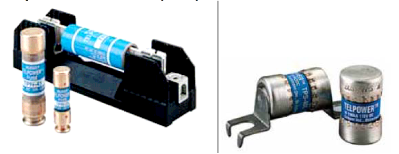
This type of fuses has been developed especially for DC shortcircuit protection and DC supplies in telecommunication devices. The fuses are normally connected to power rectifier outputs, accumulator connections or DC supplies.
All features of NV TELECOM fuses are adapted mostly to the equipment operation conditions to power the telecommunication devices. Low loss and switching voltage enable optimal operation and circuit protection in telecommunication installation and devices. The fuse ETI TELECOM NH00 with a back-up characteristics operates in a limited current range, which is from some minimal allowed current to the rated break capacity. It is the best at high break capacity (25 kA DC) and the element is made of pure silver, resistant to aging.
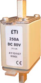
NV TELECOM fuses have been available only in the standard size NV00 for the voltages up to 80 V DC and nominal currents from 160A to 800A. According to IEC, the highest allowed currentin size NV 00 is In= 160A and the maximum allowed nominal power Pn=12W (see IEC 60269-2, Ed.3, 11/2006).
The fuse should be assemblied in a suitable fuse sectional switch. Due to fuse nominal currents up to 800A and power loss up to 38W, it is very important that NV base or fuse sectional switch has the right dimensions of connection leads and contact parts.
Market needs have shown that a new generation of NV TELECOM 170V DC with the nominal current of 175A has been prepared. We are aware that we have to respond to specific demands of customers in the field of special purpose fuses, which NV TELECOM fuses certainly are. We are ready to develop fuses with special nominal currents, not only the ones shown in the table below:

Standard, on the fuse top cover or indicator striker pin (more informatin in ETI catalogues)
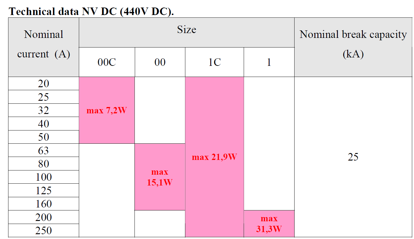
NV DC
On gaining certifications, fuse producers have tested only AC voltages ( 400C AC, 500V AC or 690V AC). As the cost has been limited and the demand low, the tests on DC voltages have been an exception rather than a rule – usually 500V fuses have been declared to be 250V DC.
As new applications have been developing, like rectifier power electronics, invertors and frequency generators, there has been a need of fuses being capable of breaking higher DC voltages. On the basis of customers' demands who have noticed that usual gG fuses of 500V are not sufficient enough completely, ETI has developed a new group of fuses, NV DC with a nominal voltage of 440V.
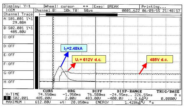
Right now our potential buyers demand fuses of nominal currents from 20A to 250A in the standard sizes of NV00C, NV00, NV1C and NV1. In the power laboratory of the Energy Measurement Infrastructure Centre in Maribor (ICEM Maribor) , we did most of shortcircuit tests on expected shortcircuit currents from 4700A to 12.100A at the circuit time constant of 20ms. An example of break of one of the fuses is shown in the oscillogram below. The expected shortcircuit current was Ip=4.720A, and the current chip at time constant 20ms was ID=2.48kA.
Standard, on the fuse top cover or indicator needle (more informatin in ETI catalogues)
1. Dr. Herbert Bessei: Competence in circuit protection
2. FERRAZ internal education materials: Fuses for Direct Current Applications
3. ETI internal education materials and test reports
